DscAlarmPanel
(New page: = DSC Alarm Panel = This Plugin connects a DSC Alarm Panel with MiOS system, via an IT-100 interface board or compatible interface. == how it works == To make it easy to handle diffe...) |
m |
||
| (7 intermediate revisions by 3 users not shown) | |||
| Line 1: | Line 1: | ||
| − | = DSC Alarm Panel | + | [[Category:Development]] |
| + | [[Category:Plugins]] | ||
| + | |||
| + | = DSC Alarm Panel - instructions for Vera2 with UI4= | ||
This Plugin connects a DSC Alarm Panel with MiOS system, via an IT-100 interface board or compatible interface. | This Plugin connects a DSC Alarm Panel with MiOS system, via an IT-100 interface board or compatible interface. | ||
| Line 7: | Line 10: | ||
To make it easy to handle different panel features, the plugin defines three different devices on the MiOS system: | To make it easy to handle different panel features, the plugin defines three different devices on the MiOS system: | ||
| − | '''main device'''[[Image(main panel1.png, align=right)]] | + | '''main device'''[[Image(main panel1.png, align=right)|[[Image:DSC_Main_panel.png|right]]]] |
| + | This represents the panel itself. The main tab contains: | ||
| + | <br> | ||
| − | *A display with any message shown by the panel's LCD screen. | + | *A display with any message shown by the panel's LCD screen. |
| − | *A text entry box to set the access code used by the plugin to access the panel. | + | *A text entry box to set the access code used by the plugin to access the panel. |
*A button to synchronize the panel's clock with Vera's. | *A button to synchronize the panel's clock with Vera's. | ||
| − | + | <br> | |
There are four 'global' alarms on the panel: | There are four 'global' alarms on the panel: | ||
| − | *Fire Key | + | *Fire Key |
| − | *Auxiliary Key | + | *Auxiliary Key |
| − | *Panic Key | + | *Panic Key |
*Auxiliary Input | *Auxiliary Input | ||
Each of these can generate an event when triggered or cleared. | Each of these can generate an event when triggered or cleared. | ||
| − | '''partition subdevices | + | |
| + | |||
| + | '''partition subdevices[[Image:DSC_Partition_panel.png|right]]''' | ||
On the main tab the device shows the partition status ('Ready', 'In Alarm', 'Disarmed', etc), and has five buttons to send commands to the partition: 'Away', 'Stay', 'Armed no Entry Delay', 'Arm with Code', 'Disarm'. | On the main tab the device shows the partition status ('Ready', 'In Alarm', 'Disarmed', etc), and has five buttons to send commands to the partition: 'Away', 'Stay', 'Armed no Entry Delay', 'Arm with Code', 'Disarm'. | ||
Events are generated on status changes. | Events are generated on status changes. | ||
| + | |||
| + | |||
'''zones or sensors''' | '''zones or sensors''' | ||
| Line 39: | Line 48: | ||
== Setup == | == Setup == | ||
| + | Before starting working on Vera the DSC Alarm device should already be configured with Partitions, Zones and Sensors. | ||
| − | If the IT-100 interface is connected to Vera with an USB-Serial adapter, there should appear a serial port device. | + | 1) On the dashboard go to the MiOS Marketplace section and in the upper right corner of this section you will find a green plus ( '''+''' ) sign. Press this button and it will open the Marketplace window (On newer firmware versions, above 1.1.1186 it will open a new tab on your browser and you will have to log in with the cp.mios.com credentials to install plugins). Search for the DSC Alarm Panel plugin and install it. You will see the plugin installed in the MiOS Marketplace section. Also in the Devices sections you will find a new device created. Press the little wrench key in the upper right corner of the newly created device and access the control window.<br> |
| − | + | You should rename this device so you can identify it easily in the future. <br> | |
| − | Partitions and zones are configured on the panel itself. Note the number of each one (partitions are numbered 1-8, zones are 1-64) and open the main panel device. Go to the 'Advanced' tab, and set three variables, all with the service ID "urn:micasaverde-com:serviceId:AlarmPanel1": | + | 2) If the IT-100 interface is connected to Vera with an USB-Serial adapter, there should appear a serial port device. You have to associate the serial port with the main panel device. Go to the '''Settings''' tab and under ''Send using:'' option select the port used to communicate with the IT-100 interface.<br> |
| + | 3) On the '''DSC Alarm Panel''' tab, under the ''Access Code'' option type your access code (4 to 6 digits)<br> | ||
| + | 4) Close the pop up window and press the ''Save'' button<br> | ||
| + | 5) Go back to the '''DSC Alarm Panel''' tab and above the ''Access Code'' option you should see the time. (this is a confirmation for you to know that Vera is communicating with the DSC)<br> | ||
| + | 6) Partitions and zones are configured on the panel itself. Note the number of each one (partitions are numbered 1-8, zones are 1-64) and open the main panel device. Go to the '''Advanced''' tab, and set three variables, all with the service ID "urn:micasaverde-com:serviceId:AlarmPanel1": <br> | ||
''''ActivePartitions' ''': A comma-separated list of the partition numbers configured on the panel. | ''''ActivePartitions' ''': A comma-separated list of the partition numbers configured on the panel. | ||
| Line 51: | Line 65: | ||
After setting these variables, close the dialog and hit the 'Save' icon. Luup will restart and the plugin will create one subdevice for each parition and zone. | After setting these variables, close the dialog and hit the 'Save' icon. Luup will restart and the plugin will create one subdevice for each parition and zone. | ||
| + | <br><br> | ||
| + | You can also check this DSC Alarm Panel [http://code.mios.com/trac/mios_dscalarmpanel installation guide] for more information. | ||
Latest revision as of 07:09, 27 May 2011
[edit] DSC Alarm Panel - instructions for Vera2 with UI4
This Plugin connects a DSC Alarm Panel with MiOS system, via an IT-100 interface board or compatible interface.
[edit] how it works
To make it easy to handle different panel features, the plugin defines three different devices on the MiOS system:
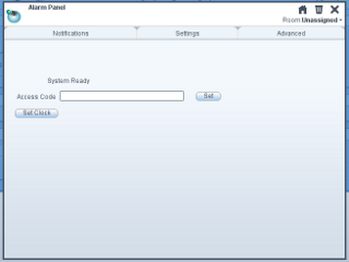
main device[[Image(main panel1.png, align=right)|]]This represents the panel itself. The main tab contains:
- A display with any message shown by the panel's LCD screen.
- A text entry box to set the access code used by the plugin to access the panel.
- A button to synchronize the panel's clock with Vera's.
There are four 'global' alarms on the panel:
- Fire Key
- Auxiliary Key
- Panic Key
- Auxiliary Input
Each of these can generate an event when triggered or cleared.
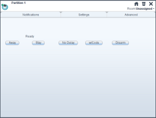
On the main tab the device shows the partition status ('Ready', 'In Alarm', 'Disarmed', etc), and has five buttons to send commands to the partition: 'Away', 'Stay', 'Armed no Entry Delay', 'Arm with Code', 'Disarm'.
Events are generated on status changes.
zones or sensors
Each zone is represented as a sensor device. Currently you can select which appears as 'Smoke sensors' and which as 'Motion sensors'. There's no functional difference between them, but a UI can list them apart, or show different icons.
Events are generated on status changes.
[edit] Setup
Before starting working on Vera the DSC Alarm device should already be configured with Partitions, Zones and Sensors.
1) On the dashboard go to the MiOS Marketplace section and in the upper right corner of this section you will find a green plus ( + ) sign. Press this button and it will open the Marketplace window (On newer firmware versions, above 1.1.1186 it will open a new tab on your browser and you will have to log in with the cp.mios.com credentials to install plugins). Search for the DSC Alarm Panel plugin and install it. You will see the plugin installed in the MiOS Marketplace section. Also in the Devices sections you will find a new device created. Press the little wrench key in the upper right corner of the newly created device and access the control window.
You should rename this device so you can identify it easily in the future.
2) If the IT-100 interface is connected to Vera with an USB-Serial adapter, there should appear a serial port device. You have to associate the serial port with the main panel device. Go to the Settings tab and under Send using: option select the port used to communicate with the IT-100 interface.
3) On the DSC Alarm Panel tab, under the Access Code option type your access code (4 to 6 digits)
4) Close the pop up window and press the Save button
5) Go back to the DSC Alarm Panel tab and above the Access Code option you should see the time. (this is a confirmation for you to know that Vera is communicating with the DSC)
6) Partitions and zones are configured on the panel itself. Note the number of each one (partitions are numbered 1-8, zones are 1-64) and open the main panel device. Go to the Advanced tab, and set three variables, all with the service ID "urn:micasaverde-com:serviceId:AlarmPanel1":
'ActivePartitions' : A comma-separated list of the partition numbers configured on the panel.
'MotionSensors' : A comma-separated list of the zone numbers that represent motion sensors.
'SmokeSensors' : A comma-separated list of the zone numbers that represent smoke sensors.
After setting these variables, close the dialog and hit the 'Save' icon. Luup will restart and the plugin will create one subdevice for each parition and zone.
You can also check this DSC Alarm Panel installation guide for more information.

