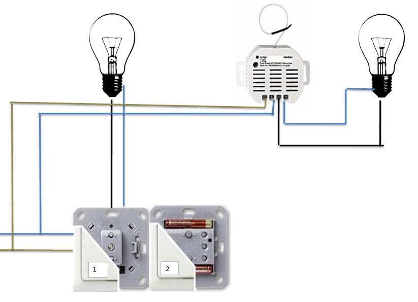
Duwi schematics
From MiOS
(Difference between revisions)
m |
|||
| (One intermediate revision by one user not shown) | |||
| Line 1: | Line 1: | ||
| − | |||
[[Category:Hardware]] | [[Category:Hardware]] | ||
| Line 16: | Line 15: | ||
'''These are the universal schematics for the setup described:'''<br> | '''These are the universal schematics for the setup described:'''<br> | ||
| − | [[Image:Duwi_Installation_schematics.JPG | + | [[Image:Duwi_Installation_schematics.JPG]]<br> |
---- | ---- | ||
'''Please view this file for the dutch instructions:''' | '''Please view this file for the dutch instructions:''' | ||
[[Media:Duwi_installatie_schema.JPG|NLD schema]] | [[Media:Duwi_installatie_schema.JPG|NLD schema]] | ||
Latest revision as of 01:37, 15 June 2013
Installation to replace a standard dual switch with a Z-Wave configuration.
This page provides information on how to install a Duwi setup in combination with a Merten receiver with the following devices;
- DUWI INTEREACT Z-WAVE DIMMER (Wall fitting)
- DUWI EVERLUX WALL switch (Can be place anywhere, battery operated)
- DUWI double frame (not depicted)
- Merten CONNECT receiver/switch (In wall fitting)
Note, This setup also works when Vera is not active.
These are the universal schematics for the setup described:
Please view this file for the dutch instructions: NLD schema
